Resonator spectroscopy
This experiment measures the resonator frequency when the qubit is in the ground state.
Description
To measure the state of a superconducting qubit, standard circuit QED setups use dispersive measurement. Here, the qubit is capacitively or inductively coupled to a readout resonator, which allows the determination of the qubit state without perturbing it.
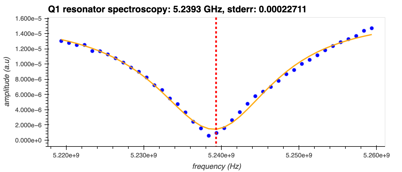
When a resonator is driven on resonance, most of the signal is reflected, resulting in a dip in the spectrum around its resonance frequency, \(\omega_r\) (see figure below). When the resonator is coupled to a qubit, however, its resonance frequency will experience a shift that's dependent on the state of the qubit1. In the two-level system (TLS) approximation, this results in a modified resonance frequency of \(\omega_{r}' \pm \chi\), where \(\omega_r'\) is the central frequency of the resonator when it's coupled to the qubit and is slightly shifted from \(\omega_r\). The sign of the dispersive shift, \(\chi\), indicates whether the qubit is in the \(|0\rangle\) or \(|1\rangle\) state. By driving the resonator with microwave radiation and observing the transmitted (or reflected) waves, it is therefore possible to determine the qubit state without destroying it.
For accurate qubit readout, the optimal resonator readout frequency must first be determined by measuring the full transmission spectrum of the resonator. This is the purpose of the Resonator Spectroscopy experiment.
Experiment steps
- With the qubit in the ground state, the readout frequency is swept over a range of values defined around the expected frequency and the resonator transmission is measured for each value.
Analysis steps
-
The amplitude of the resonator's signal is calculated as \(\sqrt{I^2 + Q^2}\), where \(I\) and \(Q\) are the in-phase and quadrature components of the transmitted signal, respectively.
-
This amplitude is plotted as a function of frequency, and the modified resonator frequency is extracted from the centre of a Fano line shape fit to the data.
-
Alexandre Blais, Ren-Shou Huang, Andreas Wallraff, S. M. Girvin, and R. J. Schoelkopf. Cavity quantum electrodynamics for superconducting electrical circuits: an architecture for quantum computation. Phys. Rev. A, 69:062320, Jun 2004. doi:10.1103/PhysRevA.69.062320. ↩
