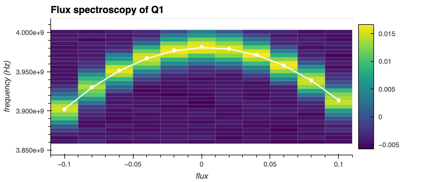
Pulsed qubit spectroscopy per flux
This experiment measures the qubit resonance frequency, \(\omega_q\), for different flux values.
Description
If two or more qubits are in close proximity and have a similar resonance frequency, frequency collisions between them can cause unintended interactions and crosstalk, reducing fidelities. To prevent these collisions and engineer high-fidelity two-qubit gates such as the iSWAP, frequency-tunable transmon qubits are commonly used as an extension of the fixed-frequency transmon qubit.
A typical architecture for these tunable qubits involves replacing the single Josephson junction (JJ) with a loop containing two junctions. This allows the Josephson energy, \(E_J\), to be tuned by applying an external flux, \(\Phi_{\text{ext}}\) 1. For enhanced robustness against flux noise, the two JJs are typically designed to be asymmetric, meaning their physical properties differ.
The effective Hamiltonian, \(H\), of the asymmetric split transmon is
where \(E_C\) is the charging energy of the qubit, \(n\) is the charge operator (typically the number of Cooper pairs transferred across the junction), and \(\phi\) is the phase difference across the junction. You can see how the Josephson energy, \(E_{J}\), has been replaced by the effective Josephson energy, \(E_{J}'(\Phi_{ext})\), which is now a function of the external flux.
Flux-tunable qubits must be characterised to locate the "sweet spot" where the qubit frequency has minimal dependence on flux, i.e., the gradient of the qubit frequency with respect to externally applied flux is zero. This helps to maximise the coherence times. In this experiment, we perform Pulsed Qubit Spectroscopy as a function of applied flux in order to determine this sweet spot.
Experiment steps
- The qubit drive frequency and external flux are swept over a range of values defined around the expected values. For each frequency-flux combination, a (constant) readout pulse is applied and the resonator's transmission is measured.
Analysis steps
-
The amplitude of the resonator's signal is calculated as \(\sqrt{I^2 + Q^2}\), where \(I\) and \(Q\) are the in-phase and quadrature components of the transmitted signal, respectively.
-
This amplitude is plotted as a function of the drive frequency and applied flux, and the qubit frequency is extracted from the centre of a Lorentzian shape fit to the data.
-
P. Krantz, M. Kjaergaard, F. Yan, T. P. Orlando, S. Gustavsson, and W. D. Oliver. A quantum engineer's guide to superconducting qubits. Applied Physics Reviews, 6(2):021318, 06 2019. doi:10.1063/1.5089550. ↩
