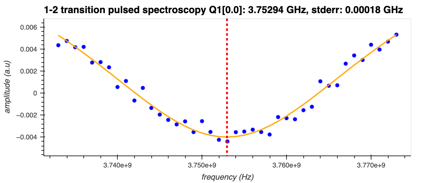
Pulsed qubit spectroscopy (1-2 states)
This experiment measures the qubit resonance frequency between the first and second excited states, \(\omega_{q12}\).
Description
The qubit resonant frequency between the first \(|1\rangle\) and second \(|2\rangle\) excited states, \(\omega_{q12}\), is related to the energy difference between the two levels (\(E_1\) and \(E_2\), respectively) through
where \(\hbar\) is the reduced Planck's constant.
\(\omega_{q12}\) can also be expressed as
where \(\omega_{q}\) is the qubit resonant frequency between the ground state \(|0\rangle\) and the first excited state \(|1\rangle\). The qubit anharmonicity, \(\alpha\), represents the difference in frequency between the 0-1 and 1-2 transitions. This anharmonicity indicates the non-linear spacing of energy levels, which is crucial for manipulating qubit states in quantum computing.
If the qubit is in the \(|1\rangle\) state and the frequency of the drive pulse matches \(\omega_{q12}\), the qubit will be (partially) excited into the \(|2\rangle\) state; if it does not, it will remain in the \(|1\rangle\) state. By sweeping the drive frequency around the expected \(\omega_{q12}\) and measuring the resonator response after a (constant) readout pulse is applied, it's possible to determine the value of \(\omega_{q12}\) 1.
In superconducting qubits, \(\omega_q\) and \(\omega_{q12}\) are usually a few GHz (in the microwave range). The anharmonicity, \(\alpha\), is typically negative (i.e. \(\omega_q>\omega_{q12}\)) and in the range of a few 100 MHz.
Experiment steps
-
A \(\pi\)-pulse with frequency \(\omega_q\) is applied to the qubit to prepare it in the first excited state \(|1\rangle\).
-
A second \(\pi\)-pulse with frequency around that expected for \(\omega_{q12}\) is applied to prepare the qubit in the second excited state \(|2\rangle\).
-
The resonator transmission is measured.
-
Steps 1-3 are repeated for different frequencies of the second \(\pi\)-pulse.
Analysis steps
-
The amplitude of the resonator's signal is calculated as \(\sqrt{I^2 + Q^2}\), where \(I\) and \(Q\) are the in-phase and quadrature components of the transmitted signal, respectively.
-
This amplitude is plotted as a function of the frequency of the second \(\pi\)-pulse, and \(\omega_{q12}\) is extracted from the centre of a Lorentzian shape fit to the data.
Note
Using the previously known value of \(\omega_q\) with the newly-obtained \(\omega_{q12}\), the anharmonicity \(\alpha\) can also be calculated.
-
Marek Pechal. Microwave photonics in superconducting circuits. PhD thesis, ETH Zürich, 2016. doi:10.3929/ethz-a-010735338. ↩
