Amplitude Rabi (0-1 states)
This experiment measures the Rabi oscillations of a qubit and calibrates the amplitude of the \(\pi\)-pulse.
Description
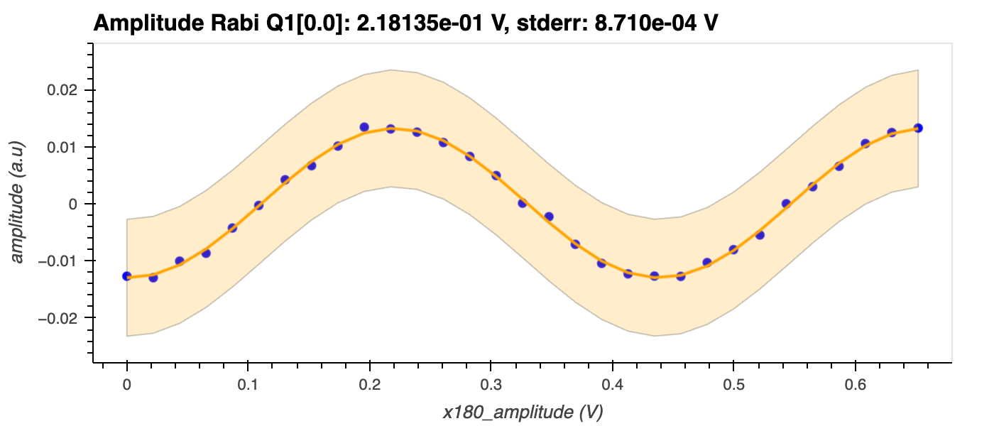
By driving a qubit with a sinusoidal signal with increasing amplitude, one can observe Rabi oscillations as the qubit oscillates between the two qubit energy levels (\(|0\rangle\) and \(|1\rangle\)). These oscillations, which can be seen in the figure below, correspond to the rotation of the qubit state around the Bloch sphere. Since harmonic oscillators do not exhibit this behaviour, Rabi oscillations serve as clear evidence that we are working with qubits, i.e., an anharmonic system1.
This experiment is also used to determine the amplitude of the \(\pi\)-pulse, which is the amplitude of the drive signal required to promote the qubit from the ground state to the excited state (\(|0\rangle \rightarrow |1\rangle\)). This transition corresponds to a rotation of \(\pi\) radians around the Bloch sphere, hence the name \(\pi\)-pulse.
Experiment steps
-
An \(R_x(\theta)\) gate (rotation of the qubit state around the \(x\)-axis by an angle \(\theta\)) is applied to the qubit while the amplitude of the driving pulse is swept over a range of values defined around the expected \(\pi\)-amplitude.
-
The resonator transmission is measured and the \(I\) and \(Q\) signals are collected for each value of the driving pulse amplitude.
Analysis steps
-
The amplitude of the resonator's signal is calculated as \(\sqrt{I^2 + Q^2}\), where \(I\) and \(Q\) are the in-phase and quadrature components of the transmitted signal, respectively.
-
The amplitude is plotted as a function of the driving pulse amplitude and a sinusoidal function is fit to it. The \(\pi\)-pulse amplitude is determined as the driving pulse amplitude that yields the first maximum of the sinusoid. For example, in the figure below, this occurs at ~0.218.
-
Mahdi Naghiloo. Introduction to experimental quantum measurement with superconducting qubits. 2019. arXiv:1904.09291. ↩
